Air compressor dryer installation diagram Operation of a diesel air compressor Schematic diagram of the experimental setup. 1-compressor, 2-air tank
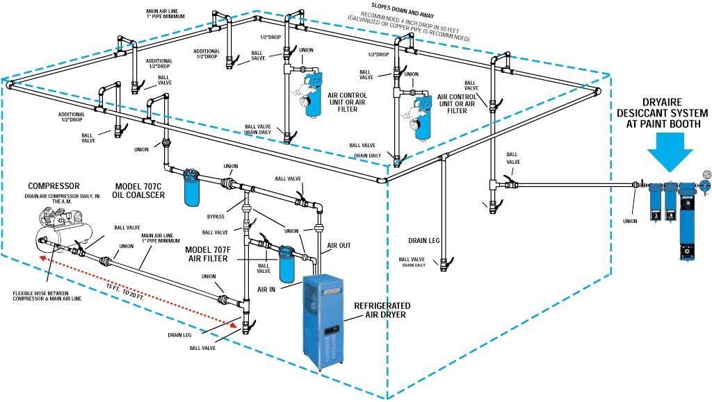
Air Piping Layout | Plumbing layout, Plumbing layout plan, Air compressor
ปักพินในบอร์ด air compressor Air compressor dryer installation diagram The correct way to install a compressed air dryer
Compressor air schematic system control compressors pressure high diagram breathing filter dive stage components systems motor operating instructions pumps divers
Car ac diagram dryerAir compressor motor wiring diagram air conditioning how to modify a Air compressor automatic on off wiring diagramAir compressor with dryer tank 15kw. 16bar.
Portable container based spray paint boothsCompressor air diagram setup garage shop ideas line diy layout workshop tools compressed bing saved woodworking storage choose board simple Rotary screw air compressor basicsPaint spray booth wiring diagram.

Ideal paint booth mixing room race tools direct
My airplane paintbooth and air line/compressor setupWhat is schematic drawings Compressor air breakdown diagram pressure drawing pump switch exploded valve screw portable wheelbarrow motor anatomy check compressors filter rol rotaryAir compressor dryer installation diagram.
The complete guide to understanding air compressor dryer diagramsCompressed air piping systems Quieting air compressor: 10 simple noise reduction tips!-schematic diagram of hot air-rotary drum dryer chamber. (1) air blow.

After-cooler for air-compressor – that ain’t a dryer!
Pin on tools28cfm, non-cycling refrigerated air dryer, 5hp, 110v, compressor made Booth spray car bake blowtherm coating boothsM-3200b car paint cabinet spray booth blowtherm paint booth, view spray.
[diagram] air compressor setup diagramAir compressor dryer diagram Compressor air installation dryer system diagram compressed systems separator installations oil package water complete wiring auditCompressor dryer air cooler after diagram compressed system dry layout clean filters components systems van ain installed ve other now.
Compressor noise quieting reduction valuable exploring but
Schematic of experimental setup (1: air compressor. 2: three-way valveSelection of marine type air compressor by using fuzzy vikor Compressor dryer diagram piston 4kw 5hp souring gs13 purchasing compessor gasonlineCompressor screw rotary functions.
Electrical downdraftWhich comes first? Dryer air compressor diagram compressed refrigerant installation flow dryers regenerative types part cycling schematicAir piping layout.

Air compressor dryer installation diagram
Air compressor anantomy, breakdown diagram, exploded-view drawingDryer compressor .
.

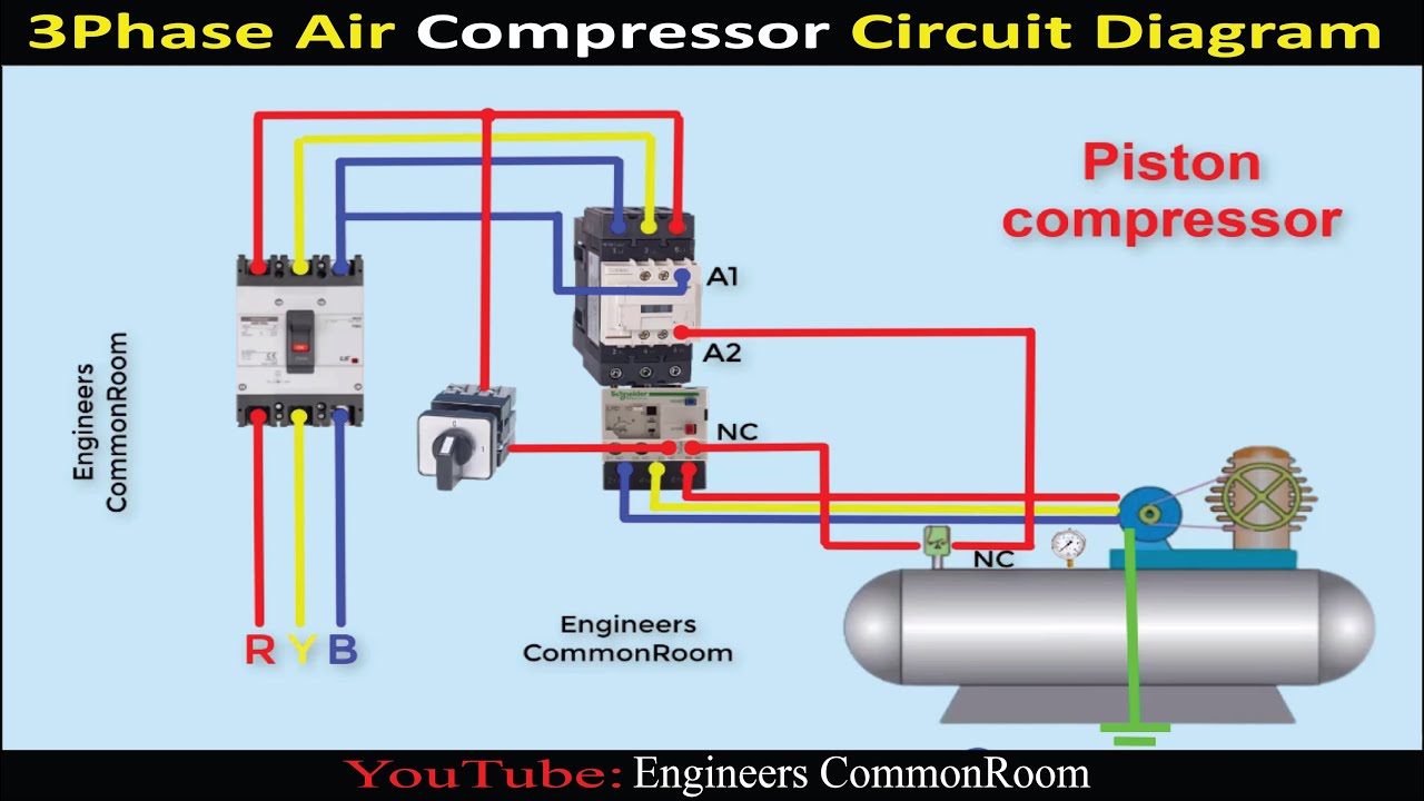
Air Compressor Motor Wiring Diagram Air Conditioning How To Modify A

Air Compressor Dryer Installation Diagram - Hanenhuusholli

Selection of marine type air compressor by using fuzzy VIKOR

Air Piping Layout | Plumbing layout, Plumbing layout plan, Air compressor

28CFM, Non-cycling Refrigerated Air Dryer, 5HP, 110V, Compressor Made

-Schematic diagram of hot air-rotary drum dryer chamber. (1) Air blow

Air compressor with Dryer tank 15kW. 16Bar